Erection Concepts and Procedures
The 16 pole Valhalla can be erected with a twelve man team in three days using only telescopic forklifts when transported by road. All lift motors are built into the king poles and all rigging travels with them. The king poles are laid out and attached to steel base plates, which accept horizontal loads of some 80 kN during initial lift of the king poles and downward pressure of 170 kN under maximum load. In firm soil the standard base plates can accept these loads.
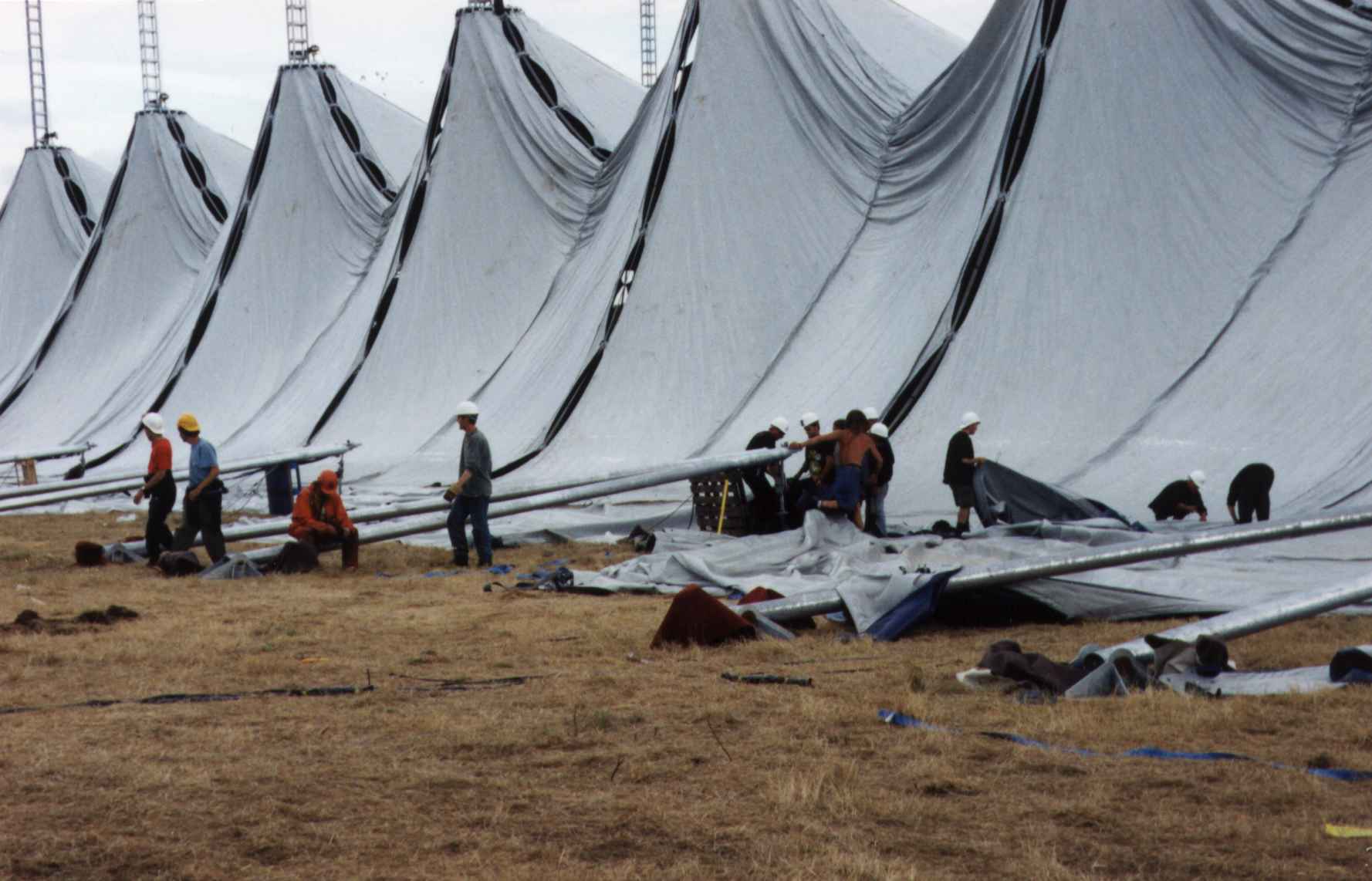
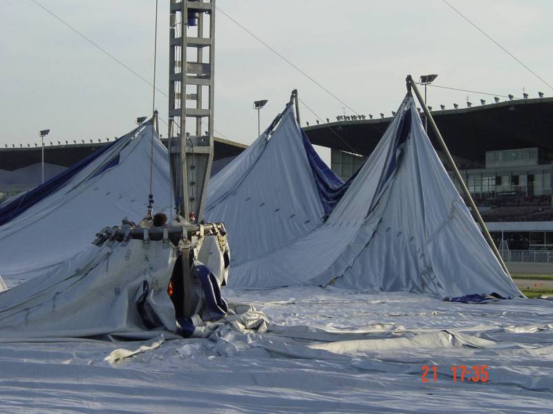
The structure is erected by first laying out and erecting the king poles, then laying out and assembling the membrane and attaching the rain covers. The bale, (lifting), rings are raised up the king poles to 50% of the height of the masts. The 'A' frames, (outer masts), are connected to the membrane and partly raised into the air with mechanical winches. When the membrane has been checked to ensure that all connections are correct the 'A' frames can be raised to the service position. The membrane can be raised to 95% of the prestress form and checked once again.
The membrane is then raised to its service height and all tie backs and tensioners checked for correct tension. At this point the tie back tensions are checked against the figures arrived at through analysis and corrected if necessary. At this point the lifting gear is made fast at the built in points and all electrical gear disconnected. The structure is now ready for interior fit out after which the walls can be installed.
4.1 Ground Anchors
Despite the efforts of the design team to minimise them, anchor forces on the Valhalla can be as high as 280 kN. Previously unused methods of temporary anchors were required and techniques developed to deploy them. Two metre lengths of screw anchor are used with a torque meter on a hydraulic motor with shear pins. When torque readings or lack of shear in the shear pin show that the anchor will not meet the expected load, an additional two metre length of anchor is inserted and screwed into the ground until the required readings are attained. The inserted anchors have a representative 20% test applied to them with a 600 kN portable test rig. If any anchor fails, all anchors are then tested. This allows the operator of the structure to be absolutely sure that the structure can meet performance targets.
Another concern is the possibility of the main masts sinking into the earth under high load. The following table gives guidance as to the allowable bearing pressures on certain soil types and the size of spreader required. Extracted from British Standard 8004. The soil loading data and information was arrived at by on site testing and compiled using data and research undertaken by Ovesen and Stromann [Ref 3].

Type of soil Allowable bearing pressure
(kN/m2) Spreader plate size
(maximum req. for this bearing pressure)
Loose sand 90 2.1m x 2.1m
Medium dense sand 100 2m x 2m
Firm clay 75 2.31m x 2.31m
Stiff clay 150 1.65m x 1.65m
The structure is one of the largest portable buildings ever built. While smaller structures have been larger when connected together and larger structures with lower wind speed capabilities have been built, there has never been a structure with the presence, the design standards, the performance capabilities and the sheer size, height and load carrying capabilities of this ground breaking structure.
It defines a new paradigm for portable structures.
References
1. Guinness World Records, Guinness Superlatives, 1999, London
2. Institution of Structural Engineers, 1995, Temporary Demountable Structures, Guide to Procurement, Design and Use, SETO, London, ISBN 1 874266 17 4
3. Ovesen, NK and Stromann, H, 1972, Design Methods for Vertical Anchor Slabs in Sand, Proceedings, Speciality Conference on Performance of Earth and Earth-Supported Structures, American Society of Civil Engineers, Vol. 2.1, pp.1481-1500