THE VALHALLA/TENSILE 1 STRUCTURE - TECHNICAL SPECIFICATIONS AND ENGINEERING
A Comprehensive Technical Analysis of the World's Largest Portable Event Venue

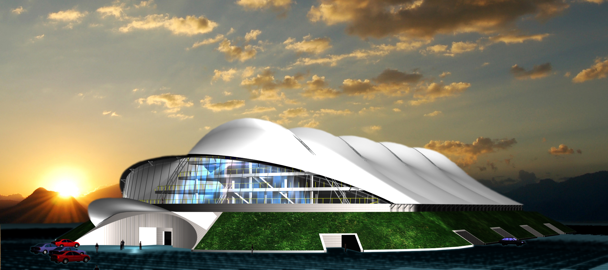
A further development of the Valhalla family is the P Span Arena, a permanently engineered version using parabolic arched to give more clearance in the centre of the floorplan. See https://www.pspan.com/ or https://www.specialstructures.com/projectlibrary/pspanarena
1. INTRODUCTION AND OVERVIEW
1.1 Structure Identity and Recognition
Tensile 1, commercially known as the Valhalla, represents the pinnacle achievement in portable membrane structure engineering. Designed by Rudi Enos in the 1990s as the largest of his portable membrane structures, Tensile 1 has established multiple world records and set new standards for what temporary event infrastructure can achieve.
World Record Recognition:
- 1998: Guinness World Record for 'Largest Portable Structure'
- 2000: Guinness World Record for 'Largest Portable Event Venue'
Scale Comparison: At 12,600m², Tensile 1 is closely followed by:
- The Kayam: 10,490m²
- The MT66 MegaDome: 8,800m²
By any standards these are the largest portable structures ever used for major events. The gap between Tensile 1 and its nearest competitor represents a substantial 20% increase in covered area, demonstrating a significant engineering advancement. Valhalla is twice the width and half as high again as the Kayam.
The Valhalla contract called for 23,456 m2 of fabric (the surface area) to be manufactured. Plus the area of the walls, so more than 40,000 m2 of type 2 structure grade fabric was used in the project. 26,000 steel components were used for the fittings of the structure, not counting the main supports.
1.2 Design Team and Engineering Provenance
Designer: Rudi Enos
- Decades of experience in temporary structures and events industry
- Member of HSE (Health & Safety Executive) Joint Advisory Committee on Entertainments (JACE)
- Member of Temporary Demountable Structures working groups
- One of a select group of engineers worldwide with expertise in long-span tension membrane structures
Engineering Execution: Special Structures Lab Ltd
- Specialists in advanced lightweight structure design
- Providing design, analysis and manufacturing support for leading manufacturers
- Specializing in tension fabric structures
Long-span structures, and in particular long-span tension membrane structures, require specialist expertise in design, analysis, manufacturing techniques, and installation procedures. Only a handful of engineers in the world have this expertise and Rudi is one of that select group.
1.3 Design Philosophy
The Valhalla portable membrane structure uses unique methods of design, manufacture and installation to achieve the project aims of devising a large-scale portable structure which could house the same events as a permanent arena.
This represented a fundamental departure from conventional temporary structures, which typically compromised on either functionality or scale when portability was required. The design challenge was to create a venue that could genuinely replicate the environmental control, acoustic properties, and infrastructure capacity of a permanent facility while remaining completely mobile.
The structure houses events in an identical way to a permanent arena and can accommodate typical touring shows and rigging setups with up to 240,000 kilograms of suspended loads. This performance standard—matching permanent facilities—became an increasingly important requirement as temporary structures moved beyond simple shelter provision to become sophisticated event venues.
2. PHYSICAL DIMENSIONS AND SCALE
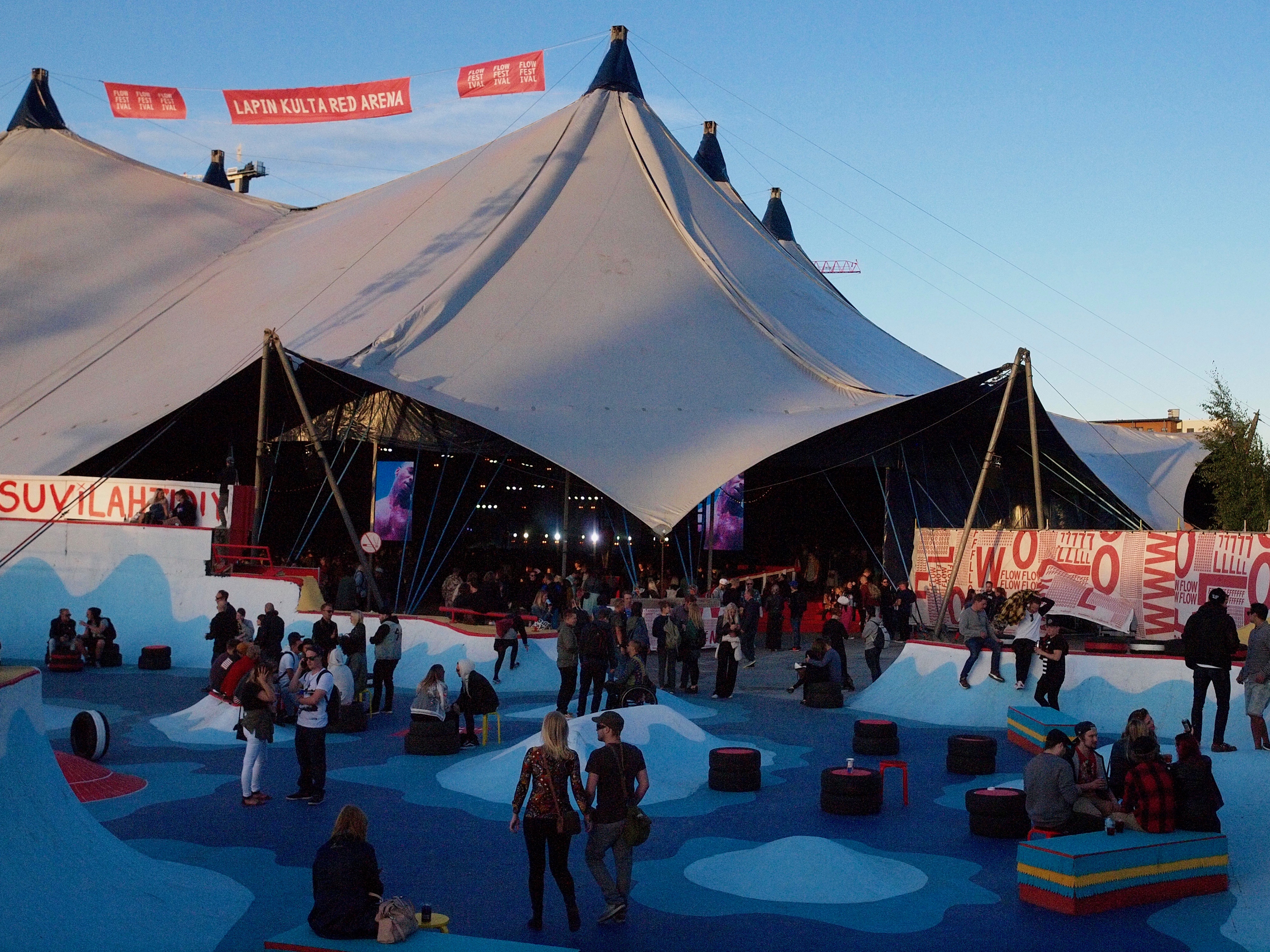
2.1 Overall Dimensions
The structure measures 86m wide, 160m long and 25m high (282ft x 600ft x 82ft), with main anchors extending to 106m x 180m (347ft x 590ft).
Covered Area:
- Total roof area: 12,600m² (approximately 135,625 square feet)
- Equivalent area: 1.26 hectares or 3.1 acres
- Area measurement: Perimeter of the roof profile when seen in plan view
Height:
- Maximum internal clearance: 25 metres (82 feet)
- Critical benefit: Exceptional clearance for complex exhibition infrastructure, suspended displays, and varied ceiling heights required for different functional zones
Anchor Footprint:
- Dimensions: 106m × 180m (347ft × 590ft)
- Perimeter: Approximately 530 meters (1,739 feet)
2.2 Enclosed Surface Area
Roof Area (Horizontal Fabric Membrane): 12,600 m² Perimeter Structural Area (Radial Webbing System): ~4,000 m² Total Structural Surface: ~16,600 m² (178,680 sq ft / 4.1 acres)
The perimeter structural system represents approximately 24% of the total structure surface, with the roof comprising 76%.
2.3 Portability and Transportation
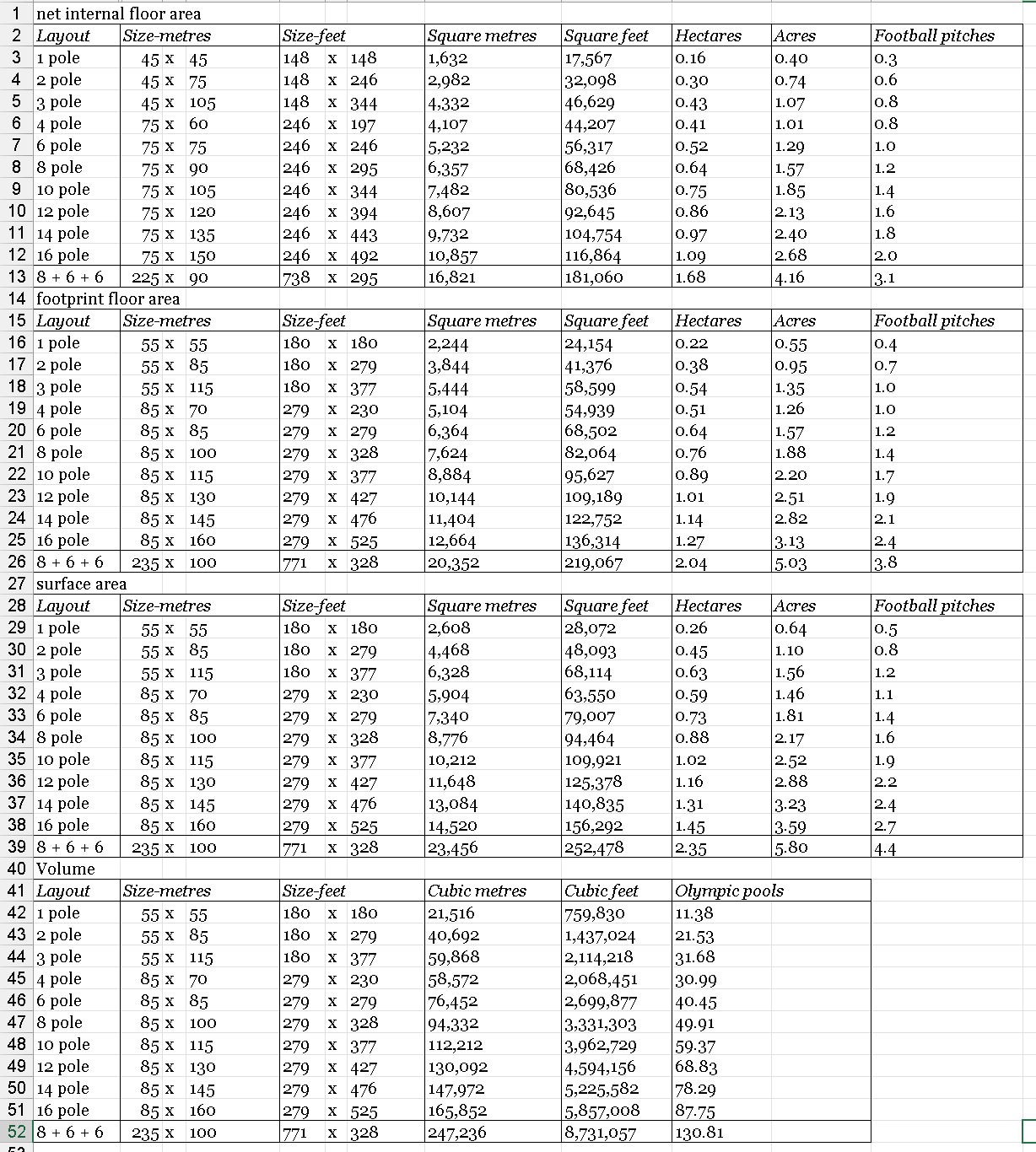
The structure can be erected in a variety of patterns up to 252,478 square feet in area and shipped around the world in 10 standard containers.
This represents an extraordinary achievement in packaging efficiency. The entire 12,600m² structure—including structural framework, membrane panels, webbing systems, anchoring systems, and connection hardware—compressed into just 10 standard ISO shipping containers.
Packaging Efficiency:
- A typical 40-foot shipping container has an internal volume of approximately 67 cubic meters
- Total shipping volume: Approximately 670 cubic meters for entire structure
- Includes: 16 central masts, 24 A-frames, membrane panels, folding trusses, all webbing systems, hardware
This packaging efficiency was achieved through:
- Modular structural components designed for nested storage
- Membrane panels that fold compactly without permanent creasing
- Folding truss systems reducing span lengths by 50%
- Rationalized connection systems minimizing the number of unique parts
- Optimized material selection balancing strength and weight
3. STRUCTURAL FRAMEWORK AND MAST SYSTEMS
3.1 Central High Mast System
Configuration:
- 16 masts arranged in 8 pairs
- Height: 25 meters (82 feet)
- Primary function: Support primary roof membrane and suspended load capacity
Construction:
- Material: Tubular steel construction
- Corrosion protection: Hot-dipped galvanized zinc finish
- Foundation connection: Steel baseplates
Mast Spacing:
- Approximately 15m centres along 160m length
- 32m between paired masts
- Creates 8 structural bays for load distribution
Structural Type:
- Steel tubular sections (300-500mm diameter), or
- Lattice trusses (600-1000mm face width)
Stabilization:
- Each central mast stabilized by 3-4 guy cables or webbing
- Guys radiating to perimeter anchors
- Guy capacity: 8,000-12,000 kg per anchor
- Total guy anchors: 48-64 (3-4 per mast × 16 masts)
3.2 Tubular Steel A-Frame Intermediate Support System

Configuration:
- 24 tubular steel A-frames deployed throughout structure
- Height: 9 meters (29.5 feet)
- Distribution: Strategic positions creating comprehensive support grid
- Spacing: Approximately 15-20m centers
Construction:
- Material: Tubular steel
- Configuration: Inverted V-shape (A-frame geometry)
- Corrosion protection: Hot-dipped galvanized zinc finish
- Foundation connection: Steel baseplates
Primary Functions During Erection:
-
Membrane Lifting Support:
- Provide intermediate support points for progressive membrane raising
- Enable controlled, systematic installation of 12,600m² fabric
- Reduce risk during installation by creating manageable lifting segments
- Allow systematic installation from center outward or perimeter inward
-
Anti-Twist Control:
- Prevent radial twist of membrane during lifting process
- Maintain proper fabric orientation as structure is tensioned
- Ensure correct load distribution during pre-tensioning
- Control geometry development during progressive tensioning sequence
Structural Role During Operation:
-
Intermediate Height Support:
- Provide geometry control points between 25m central masts and ground
- Reduce unsupported membrane spans
- Create additional stability nodes in structural system
-
Wind Resistance:
- Additional stability against wind-induced flutter
- Intermediate resistance to uplift forces
- Improved overall structural damping
-
Load Distribution:
- Distribute roof loads reducing concentrated forces
- Create multiple load paths improving redundancy
- Provide backup support for membrane geometry under varying loads
A-Frame Geometry Benefits:
- Inverted V-configuration provides inherent lateral stability
- Self-supporting during installation
- Lightweight while maintaining structural capacity
- Transportable as compact components
- Quick assembly without specialized equipment
Foundation Requirements:
- Steel baseplate connection at each leg
- Foundation anchors: 3,000-5,500 kg typical loading
- 24 A-frame foundation anchors total
- Lower loads than central masts due to intermediate support role
3.3 Total Primary Vertical Support Framework
Complete Mast System:
- 16 central masts at 25m height
- 24 A-frames at 9m height
- Total: 40 primary vertical support elements
Structural Hierarchy:
- Upper level (25m): 16 central masts supporting primary roof loads and suspended equipment
- Intermediate level (9m): 24 A-frames providing geometry control and erection support
- Ground level: Foundation anchor system
This multi-height framework creates a sophisticated three-dimensional structural system with exceptional stability and redundancy.

4. CORROSION PROTECTION AND MATERIAL DURABILITY
4.1 Hot-Dipped Galvanized Zinc Protection
All structural steelwork throughout the Tensile 1 structure features hot-dipped galvanized zinc coating. This comprehensive corrosion protection system is critical for temporary structures experiencing:
- Multiple assembly/disassembly cycles creating surface wear
- Exposure to diverse climatic conditions across global deployments
- Long-term storage between events in varying humidity conditions
- Contact with ground conditions during installation
- Transportation-induced abrasion and handling wear
4.2 Hot-Dip Galvanizing Process
The galvanizing process involves:
- Surface preparation: Degreasing and pickling removing mill scale and contaminants
- Fluxing: Prevents oxidation before zinc immersion
- Zinc immersion: Complete immersion in molten zinc (approximately 450°C)
- Metallurgical bonding: Creates zinc-iron alloy layers
- Cooling: Produces durable, uniform protective coating
4.3 Performance Characteristics
Coating Specifications:
- Coating thickness: 85-100 microns typical for structural sections
- Service life: 50+ years in moderate atmospheric conditions
- Service life (harsh): 20-30 years under harsh conditions
- Weight: Approximately 600-850 g/m² of coating
Durability Benefits:
- Abrasion resistance: Superior to paint systems for handling during repeated installations
- Coverage: Complete coating including internal surfaces, weld areas, and connection points
- Maintenance: Self-healing properties through zinc sacrificial protection
- Visual identification: Distinctive gray metallic finish
- Weld compatibility: Galvanized after fabrication ensuring weld zones fully protected
Handling Benefits:
- Resistant to damage during transportation
- Tolerates repeated connection/disconnection cycles
- No touch-up painting required between installations
- Maintains professional appearance throughout service life
Economic Benefits:
- No ongoing painting or maintenance costs
- Extended component replacement intervals
- Reduced lifecycle costs compared to painted alternatives
- Protected capital investment over decades
4.4 Application to Tensile 1 Components
GalvanisedAn estimated Components:
- All 16 central masts (tubular steel or lattice construction)
- All 24 A-frame structures (tubular steel)
- 8 folding steel trusses
- All steel baseplates (critical for ground-contact components)
- All structural connection hardware
- Guy cable fittings and attachment hardware
Total Protected Steelwork:
- Estimated 60-80 tonnes of structural steel
- Comprehensive protection ensures decades of service life
- Multiple installations across varied climates without degradation
5. FOUNDATION SYSTEMutilise
5.1 Steel Baseplate Foundation Connection System
All mast structures throughout Tensile 1 galvanised steel baseplates for foundation connections. This standardized system provides consistent, reliable load transfer across all 40 primary vertical supports plus perimeter anchor points.
Baseplate Design:
- Material: Heavy-duty steel plate
- Thickness: 25-50mm typical, depending on load magnitude
- Dimensions: 500mm-1000mm square or circular
- Corrosion protection: Hot-dipped galvanized zinc coating
- Connection: Multiple bolt holes for anchor attachment
- Leveling: Shim plates or adjustable feet for precise verticality
Foundation Connection Strategy:
- Baseplates bolt to screw anchor head assemblies or anchor connection frames
- Load transfer from mast through baseplate to anchor system
- Adjustable connections allow fine-tuning of mast position and verticality
- Quick-release provisions enable rapid dismantling
Load Distribution Benefits:
- Baseplates spread concentrated mast loads over larger foundation area
- Reduce bearing pressure on screw anchor heads
- Accommodate moment loads (bending forces) from eccentric loading
- Standardized connection details simplify installation procedures
Application Across Structure:
- 16 central mast baseplates (highest capacity)
- 24 A-frame baseplates (intermediate capacity)
- Perimeter anchor connection plates
- Guy anchor attachment plates
Installation Advantages:
- Standardized system across all foundation points
- Simplified crew training (one connection type)
- Interchangeable components
- Rapid installation and removal
- Precise leveling capability critical for membrane geometry
5.2 Screw Anchor Foundation Technology
Tensile 1 employs screw anchors (helical anchors) as the primary ground connection method. This foundation technology is particularly suited to portable structures requiring temporary installation and complete site restoration.
Screw Anchor Technology:
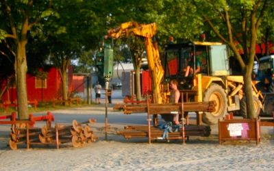
Scre anchors installation at Roskilde festival

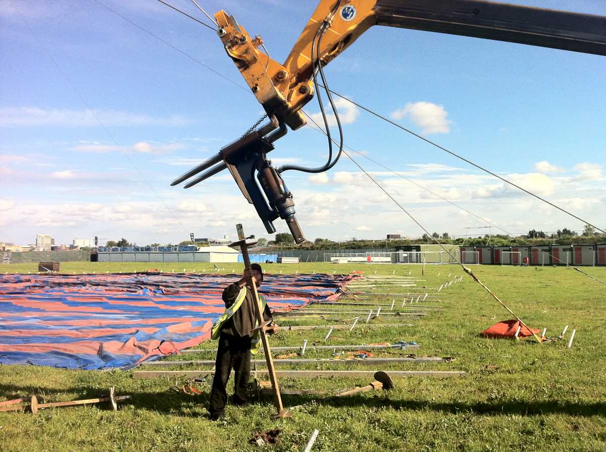
Screw anchors, up to 28, 000 kilogrammes holding!
Screw anchors consist of steel shafts with helical bearing plates welded along their length. The anchor is rotated into the ground, with the helical plates cutting through soil and advancing downward like a screw thread.
Capacity Development:
- Bearing capacity: Helical plates bear against undisturbed soil below installation depth
- Shaft friction: Skin friction along central shaft augments capacity
- Combined action: Multiple helical plates distribute load over substantial soil volume
Installation Method:
- Mechanical installation using hydraulic drive heads
- Typically mounted on excavators or purpose-built installation rigs
- Rotation speed: 8-20 RPM typical
- Installation time: 5-15 minutes per anchor depending on depth and soil conditions
Advantages for Portable Structures:
-
Installation Speed:
- Rapid deployment without excavation or concrete curing delays
- Multiple anchors installed simultaneously using several rigs
- Site preparation minimal compared to cast foundations
-
Immediate Loading:
- Unlike concrete anchors requiring 7-28 days curing
- Screw anchors proof-loaded and commissioned immediately after installation
- Structure erection can proceed without foundation curing delays
-
Minimal Site Disturbance:
- Installation creates no spoil requiring disposal
- Minimal ground disturbance
- Essential for venues where turf and subsurface infrastructure require protection
-
Complete Removability:
- Anchors completely extracted after event
- Site restored to original condition
- Critical for temporary event permitting
-
Predictable Capacity:
- Load testing of trial anchors verifies design assumptions quickly
- Adjustment of specifications possible if ground conditions vary
- Installation torque correlation provides real-time capacity verification
-
Site Adaptability:
- If anchors encounter unexpected conditions (buried services, rock, variable strata)
- Installation equipment relocates and installs at adjusted positions
- Flexible approach accommodates site constraints
5.3 Anchor Load Capacity and Distribution
Maximum Design Capacity:
- Critical anchor capacity: 20,000 kg (20 tonnes / 44,000 lbs)
- Applied at highest-stressed positions (central mast foundations, major valleys, corners)
Load Characteristics:
Anchor loads in tension membrane structures exhibit several important characteristics:
- Primarily tensile: Most anchor loads pull upward and outward, resisting membrane pre-tension and wind uplift forces
-
Load variation: Anchors at different positions experience different magnitudes
- Central mast foundations: Highest loads (15,000-20,000 kg)
- A-frame foundations: Intermediate loads (3,000-5,500 kg)
- Guy anchors: Medium loads (5,000-12,000 kg)
- Valley anchors: Medium-high loads (10,000-15,000 kg)
- Radial webbing anchors: Lower loads (700-1,200 kg working load)
- Cyclic loading: Wind events create fluctuating loads as membrane deflects
- Combined loading: Anchors resist both vertical (uplift) and horizontal (sliding) force components
- Suspended load contribution: 100,000 kg of suspended equipment ultimately transfers through mast structures to specific anchor points
Anchor Field Distribution:
Anchor Type
Quantity
Capacity Each
Total Capacity
Central Mast Foundations
16
20,000 kg
320,000 kg
A-Frame Foundations
24
5,000-8,000 kg
120,000-192,000 kg
Central Mast Guys
48-64
10,000 kg
480,000-640,000 kg
Valley/Intermediate Anchors
20-30
12,000 kg
240,000-360,000 kg
Radial Webbing Ground Anchors
350-360
3,500 kg
1,225,000-1,260,000 kg
TOTAL
458-494
Variable
~2,385,000-2,772,000 kg
Average Loading:
- Total anchor field ultimate capacity: 2.4-2.8 million kg
- Average load per anchor: 1.8-2.8 tonnes under typical combined loading
- Maximum loads concentrated at critical positions (central masts)
Safety Factors:
Screw anchor design typically employs factors of safety of 2.0-3.0 against ultimate capacity:
- 20,000 kg working load anchor demonstrates 40,000-60,000 kg proof load capacity
- Ensures adequate margin against soil variability, installation quality variations, unforeseen load increases
- Accounts for cyclic loading effects and long-term creep in cohesive soils
Installation Verification:
Each screw anchor installation verified through:
- Installation torque monitoring (correlating rotational torque to capacity)
- Proof load testing of representative anchors (20-30% of total population)
- Displacement monitoring during proof loading (acceptable: <25mm at proof load)
- Visual inspection of anchor head connections
- Documentation of installation depths and torque values
6. HYBRID WEBBING AND FABRIC MEMBRANE SYSTEM
6.1 Design Concept - Hybrid Material System
The webbing sub system clearly shown here.
Tensile 1 represents a sophisticated hybrid design combining two distinct structural materials optimized for their specific structural zones:
System 1: Horizontal Roof (Fabric Membrane)
- 12,600m² Type 2 blackout PVC-coated polyester fabric
- OptimisedOptimised for biaxial stress conditions
- Weather-tight enclosure
- Complete light control for exhibition applications
System 2: Perimeter Structure (Radial Webbing)
- 350-360 individual high-strength polyester webbing straps
- optimising for uniaxial tension
- Lightweight construction
- Efficient load path geometry
This hybrid approach represents a departure from conventional membrane structures that typically employ either:
- All-fabric systems (continuous fabric membrane for roof and walls)
- All-cable systems (steel wire rope for all primary load paths)
Innovation: Tensile 1 proved that hybrid systems Plasticised material selection by structural zone could achieve equivalent or superior performance with reduced weight, improved functionality, and simplified fabrication.
6.2 Horizontal Roof Membrane Specification
Material Classification:
- Type: Type 2 PVC-coated polyester fabric
- Specification: Blackout membrane
- Area: 12,600 m²
Technical Specifications:
- Base fabric: High-tenacity polyester yarns, balanced weave construction
- Coating: Plasticized PVC applied to both faces
-
Tensile strength: 4,000 N/5cm in both warp and weft directions
- Translates to approximately 800 kg force per 5cm strip width
- Weight: 850-950 g/m²
- Thickness: 0.7-0.9mm
- Total membrane weight: Approximately 11,340 kg
Strength Rating Context:
- Light canopy fabrics: 1,500-2,500 N/5cm
- Medium architectural fabrics: 3,000-4,500 N/5cm (Tensile 1 here)
- Heavy-duty structural fabrics: 5,000-7,000 N/5cm
- Specialized high-strength fabrics (PTFE-glass): 8,000+ N/5cm
The 4,000 N/5cm selection represents optimal balance between structural performance, weight, handling characteristics, and cost for a structure of this scale.
Blackout Specification:
Unlike translucent architectural fabrics permitting 8-15% light transmission, blackout membranes incorporate opaque pigments or reflective layers preventing light penetration.
Blackout Benefits:
- Projection and multimedia displays without daylight washout
- Controlled exhibition lighting independent of exterior daylight
- Thermal management by reflecting solar radiation
- Privacy for certain programmatic functions
- Consistent internal environment regardless of time of day
- Professional exhibition standards (500-1000 lux at display surfaces)
Membrane Performance:
- UV resistance: PVC coating protects polyester from degradation
- Flame resistance: Self-extinguishing, low flame spread
- Temperature range: -30°C to +70°C operational range
- Service life: 15-20 years with proper maintenance
- Cleanability: Washable surface for maintaining appearance
6.3 Roof Webbing Belt System (No Steel Cable)
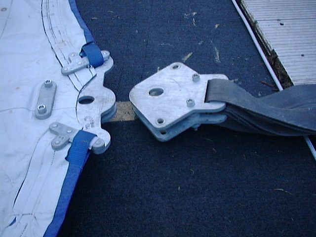
Massive steel plates for up to 60,000 kilos force in the roof.
For the horizontal roof structure, Tensile 1 employs high-strength webbing belts for all primary tension elements—ridge belts, valley belts, and edge belts supporting the fabric membrane. This represents an innovative departure from conventional large-span membrane structures, which typically rely on wire rope for primary load paths.
Roof Webbing Belt Characteristics:
- Material: Polyester (PET) continuous filament yarns
- Construction: Tightly woven, heat-set to minimize elongation
- Working load capacity: Individual belts rated from 5 to 60 tonnes depending on position
- Width: 50mm to 200mm depending on load requirements
- Thickness: 5-8mm
- Breaking strength: Typically 5:1 to 8:1 safety factor above working loads
Advantages of Webbing Over Wire Rope:
-
Weight Reduction:
- Polyester webbing weighs approximately 1/7th that of equivalent strength steel wire rope
- Dramatically reduces dead loads and transportation weight
- Enables larger structures without proportional foundation increases
-
Handling Safety:
- Webbing lacks sharp broken wire hazards of steel cable
- Improved worker safety during installation and maintenance
- Reduced PPE requirements
- Safer in confined spaces during installation
-
Damage Tolerance:
- Unlike wire rope (catastrophic failure if single strand breaks)
- Woven webbing degrades gradually
- Provides visible warning of damage
- Allows inspection without specialized equipment
-
Flexibility:
- Webbing wraps around smaller radii than wire rope of equivalent strength
- Simplifies connection details
- Reduces stress concentrations at terminations
- Easier routing through complex geometry
-
Corrosion Immunity:
- Synthetic fibers unaffected by moisture
- No galvanizing requirements
- No corrosion maintenance
- Consistent strength throughout service life
-
Acoustic Properties:
- Webbing dampens vibration better than steel cable
- Reduces structure-borne noise from wind-induced oscillations
- Improved acoustic environment for events
-
Storage and Packaging:
- Webbing coils compactly
- No spring-back characteristic of wire rope
- Improves packaging efficiency
- Easier handling during installation
Load Distribution Hierarchy:
The roof webbing belt system distributes loads through a hierarchical network:
- Ridge belts: Major load-carrying webbing spanning between 8 mast pairs, defining primary structural geometry
- Valley belts: Webbing along valley lines transferring loads to ground anchors
- Edge belts: Perimeter webbing defining membrane boundaries and transferring edge loads to radial perimeter webbing system
- Secondary belts: Intermediate webbing elements controlling membrane shape and distributing loads
- Membrane-to-webbing connections: Specialized clamp or sewn connections transferring membrane tension into webbing load paths
Connection Details:
Webbing-to-membrane connections employ:
- Sewn pockets: Membrane edges folded and heat-welded creating pockets through which webbing threads
- Bolted clamps: Aluminum or stainless steel clamp bars securing membrane to webbing at intervals
- Load transfer patches: Reinforced membrane zones distributing concentrated webbing loads
- Adjustable connections: Tensioning devices allowing fine-tuning during installation
6.4 Radial Webbing Perimeter Structural System
The perimeter structural system employs 350-360 individual radial webbing straps creating the perimeter enclosure connecting the high central roof to the ground-level perimeter.
System Configuration:
- Deployment pattern: Radially from roof perimeter connection points to ground anchors
- Number of straps: 350-360 individual radial straps
- Spacing: Every 1.5 meters around 530-meter perimeter
- Orientation: Steeply angled (60-75° from horizontal)
Webbing Specifications:
- Material: High-strength polyester webbing
- Breaking strength: 3,500 kg per strap
- Working load: 700-1,200 kg per strap (2.9:1 to 5:1 safety factor)
- Width: 50-75mm
- Length: Variable 8-12 meters depending on deployment height and anchor setback
- Total system weight: Approximately 1,750 kg (350 straps × 10m average × 0.5 kg/m)
Perimeter Structural Area:
- Calculation: Perimeter (530m) × Average deployment height (7.5m) = 3,975 m²
- Rounded: Approximately 4,000 m² perimeter structural area
- Percentage of total: 24% of total structural surface (4,000m² of 16,600m² total)
Connection System:
Upper Connections (Roof Perimeter):
- Heavy-duty connection plates or rings at roof perimeter
- Multiple webbing straps converging at perimeter connection points
- Adjustable tensioning hardware (turnbuckles, ratchets, cam buckles)
- Connection capacity: 3,500-5,000 kg per attachment point
Lower Connections (Ground Anchors):
- Individual screw anchors for each webbing strap, or
- Multiple straps converging at shared anchor points
- Connection hardware rated for 3,500+ kg
- Adjustable tensioning at ground level for fine-tuning
Load Path:
- Roof membrane edge → edge webbing → perimeter connection point → radial webbing strap → ground anchor
- Direct, efficient load path aligned with force vector
- Each strap independent (failure of one ≠ system failure)
Structural Capacity:
Per-Strap Loading Under Design Conditions:
- Pre-tension: 400-700 kg
- Wind contribution: 500-900 kg
- Roof edge contribution: 225-375 kg
- Total working load: 1,125-1,975 kg per strap
- Safety factor: 3,500 kg ÷ 1,200 kg = 2.9:1 typical
Total System Capacity:
- Working load capacity: 350 straps × 1,200 kg = 420,000 kg (420 tonnes)
- Ultimate capacity: 350 straps × 3,500 kg = 1,225,000 kg (1,225 tonnes)
System Benefits:
-
Weight Reduction:
- Webbing vs. fabric: Saves 3,000-3,500 kg for 4,000m² area
- Webbing weighs ~1/7th that of equivalent fabric
-
Structural Efficiency:
- Radial pattern naturally aligned with load paths
- Uniaxial stress (vs. biaxial required for fabric)
- Each strap independent load path
-
Perimeter Enclosure Characteristics:
- 1.5m spacing creates structural perimeter system
- Appropriate enclosure for application
- Reduced wind loading compared to solid enclosure
-
Installation Simplicity:
- Individual straps deployed independently
- No seaming or panel connection required
- Strap-by-strap tensioning adjustment
- Simplified replacement if individual straps damaged
-
Load Redundancy:
- 350-360 independent load paths
- Failure of individual strap = minimal impact
- Progressive failure prevented by discrete load paths
- Superior to continuous fabric (tear propagation risk)
-
Cost Efficiency:
- Webbing less expensive than fabric per linear meter
- Reduced fabrication costs (no complex cutting/seaming)
- Lower maintenance requirements
- Simplified quality control (identical straps)
-
Adaptability:
- Openings created by omitting webbing straps
- Infill panels installed between webbing as needed
- Height variations accommodated by different strap lengths
- Site-specific customization possible
6.5 Hybrid System Integration
The two systems connect at the perimeter where the horizontal roof membrane edge meets the radial webbing deployment points:
Integration Sequence:
- Horizontal roof membrane develops edge loads
- Edge loads transfer to edge webbing belts
- Edge webbing transfers to perimeter connection points
-
Perimeter connection points become convergence for:
- Horizontal roof edge loads (inward/downward)
- Radial webbing connections (outward/downward to anchors)
- Radial webbing straps transfer combined loads to ground anchors around perimeter
Load Transfer Details:
- Fabric membrane: Biaxial stress state (tension in warp and weft)
- Transition zone: Load transfer from biaxial membrane to uniaxial webbing
- Connection detail transfers vertical component into radial webbing
- Horizontal components resolved into ridge/valley webbing
- Radial webbing: Uniaxial tension in each strap
This integration creates continuous load path from high central roof (25m masts + 240 tonnes suspended) through perimeter transition to radial webbing system and ultimately to extensive ground anchor field.
7. SUSPENDED LOAD SYSTEM - 240,000 KG CAPACITY
7.1 System Overview and Capacity
The Tensile 1 structure provides a total suspended load capacity of 240,000 kilograms (240 tonnes / 529,000 lbs) distributed across the 8 central mast pairs. This extraordinary capacity positions Tensile 1 in the performance range of mid-sized permanent arenas, representing a remarkable achievement for a completely portable structure.
Capacity Comparison:
- Small permanent venues: 50-100 tonnes capacity
- Tensile 1: 240 tonnes capacity
- Mid-sized arenas: 200-400 tonnes capacity
- Large arenas/stadiums: 500-1000+ tonnes capacity
Rigging Density:
- 240,000 kg across 12,600m² roof
- Approximately 19 kg/m² suspended load capacity
- Remarkably high for portable membrane structure
7.2 Load Distribution Per Mast Pair
Each of the 8 central mast pairs is engineered to support 30,000 kilograms (30 tonnes / 66,000 lbs) of suspended load.
Capacity Breakdown Per Mast Pair:
-
Primary Truss Loading: 20,000 kg UDL
- Purpose-built folding steel trusses between mast pairs
- Uniformly Distributed Load (UDL) capacity
- Rigid platform for equipment attachment
-
Bale Ring Loading: 5,000 kg Additional
- Structural attachment points on mast structures
- Localized concentrated loads
- Independent of truss system
Total Per Pair: 20,000 kg + 5,000 kg = 30,000 kg Total System: 8 pairs × 30,000 kg = 240,000 kg
7.3 Purpose-Built Folding Steel Truss System
Truss Configuration:
- Quantity: 8 folding trusses (one per mast pair)
- Span: 8-12m (distance between paired masts)
- Capacity: 20,000 kg UDL per truss
- Material: Structural steel tubular or angular sections
- Corrosion protection: Hot-dipped galvanized zinc finish
Folding Mechanism:
- Mid-span hinge allowing truss to fold
- Reduces to two half-length sections for transportation
- 50-60% reduction in transportation volume
- Quick-release pins or bolted connections for assembly/disassembly
Structural Design:
- Depth: 800-1200mm depending on span and load requirements
- Section: Adequate modulus for 20,000 kg UDL
- Load distribution: Engineered for distributed loading patterns
- Connection capacity: End connections rated for 10,000+ kg reactions
UDL (Uniformly Distributed Load) Specification:
The 20,000 kg UDL capacity means each truss supports equipment distributed along its length:
- Lighting bars with fixtures every 1-2 meters
- Rigging tracks for moving displays
- Speaker arrays distributed across span
- Projection equipment and screens
- Decorative elements and signage
- HVAC distribution components
- Electrical distribution (cable trays, transformers)
Installation:
- Trusses installed after membrane tensioning complete
- Connects to mast tops via heavy-duty hardware
- Quick-connect systems enable rapid installation
- Accessible for rigging crews during equipment loading
Transportation Efficiency:
- 8 trusses fold into 16 half-sections
- Compact packaging within container system
- Reduced handling requirements
- Simplified logistics
7.4 Bale Ring System
System Description: Bale rings are structural attachment points integrated into the mast structures, providing additional rigging capacity independent of the truss grid.
Configuration:
- Heavy-duty steel plates welded or bolted to mast structure
- Reinforced connection points rated for specified loads
- Multiple attachment positions at different heights on masts
- Quick-connect hardware (shackles, carabiners, rated connections)
Capacity:
- 5,000 kg additional capacity per mast pair
- May be distributed as 2,500 kg per mast, or concentrated as needed
- Independent of truss loading
Applications:
- Concentrated loads: Single heavy items (large speakers, projection equipment)
- Backup rigging points: Redundancy for critical suspended elements
- Architectural lighting: Focused spotlights and accent fixtures
- Decorative installations: Suspended sculptures, banners, thematic elements
- Specialized equipment: Items requiring specific positioning outside truss grid
Flexibility:
- Rigging positions not constrained to truss grid
- Height variation possible using different mast attachment points
- Quick reconfiguration for different event requirements
- Independent tensioning and adjustment
7.5 Typical Load Allocation
For a typical exhibition deployment utilizing the 240,000 kg capacity:
Lighting Systems (60,000-90,000 kg):
-
General illumination: 40,000-60,000 kg
- Even distribution across 12,600m² providing 200-300 lux ambient
-
Accent/display lighting: 15,000-25,000 kg
- Focused fixtures highlighting specific zones
-
Emergency/safety lighting: 3,000-5,000 kg
- Meeting egress requirements
Audio-Visual Systems (10,000-17,000 kg):
- Projection equipment: 2,000-4,000 kg
- Speaker systems: 5,000-8,000 kg
- Video displays and monitors: 3,000-5,000 kg
Exhibition Infrastructure (23,000-35,000 kg):
- Suspended signage and wayfinding: 10,000-15,000 kg
- Graphics, banners, decorative elements: 8,000-12,000 kg
- Rigging infrastructure (cable trays, distribution): 5,000-8,000 kg
Building Services (16,000-25,000 kg):
- HVAC distribution components: 8,000-12,000 kg
- Electrical distribution: 6,000-10,000 kg
- Communications equipment: 2,000-3,000 kg
Safety Systems (6,000-11,000 kg):
- Emergency lighting and signage: 2,000-4,000 kg
- Fire detection/suppression: 1,000-2,000 kg
- Structural safety cables and hardware: 3,000-5,000 kg
Reserve Capacity (60,000-100,000 kg):
- Event-specific requirements
- Future additions during event
- Safety margins beyond calculated loads
- Contingency for equipment changes
Total Typical Allocation: 175,000-178,000 kg of 240,000 kg capacity Reserve: 62,000-65,000 kg (26-27% reserve)
7.6 Structural Load Transfer
Load Path Sequence:
- Equipment suspended from folding trusses or bale rings
- Trusses transfer loads to mast tops (10,000 kg reaction each end)
- Loads travel down masts (vertical: 15,000 kg per mast from 30,000 kg pair)
- Mast base connections transfer to steel baseplates
- Foundation anchors resist resulting forces
Mast Loading Considerations:
- Vertical loads: Dead weight of suspended equipment
- Eccentric loads: Asymmetric loading creating bending moments
- Dynamic loads: Movement of equipment, wind-induced oscillation
- Combined with membrane loads: Mast tops also anchor ridge webbing under high tension
Foundation Impact:
- Suspended loads create concentrated forces at 16 mast foundations
- Central mast foundation anchors: 15,000 kg (suspended) + 5,000-8,000 kg (membrane/structure)
- Total per central mast foundation: 20,000-23,000 kg
- Requires 20,000 kg anchor capacity at these critical positions
Guy System Loading:
- Eccentric suspended loads increase guy tensions
- Asymmetric rigging creates additional moments
- Guy systems (3-4 per mast) stabilize masts against eccentric loading
- Combined loading requires robust guy anchor capacity (8,000-12,000 kg)
7.7 Safety Factors and Certification
Engineering Practice:
-
Static loads: 5:1 safety factor minimum
- 20,000 kg working load = 100,000 kg ultimate strength
-
Dynamic loads: 8:1 or higher safety factor
- Accounts for impact and shock loading
-
Connection hardware: 10:1 safety factor
- Shackles, carabiners, rigging points
Certification Requirements:
- All suspended load systems certified by qualified riggers
- Truss load testing verifying 20,000 kg UDL capacity
- Progressive loading protocol during installation
- Deflection monitoring as equipment added
- Daily inspections during event operation
- Load monitoring on highest-stressed mast pairs
- Secondary safety cables on critical suspended elements
Worst-Case Loading Scenario: The structure engineered to maintain adequate safety margins under:
- Maximum design wind event (45-53 m/s gusts)
- Full suspended load (240,000 kg installed)
- Peak occupancy (4,000-7,000 people)
- All dead loads (structure, staging, exhibitions)
Under this combination, structure maintains integrity with adequate strength reserves.
8. PRE-TENSIONING AND ERECTION METHODOLOGY
8.1 Role of A-Frames in Erection Process
The 24 tubular steel A-frames at 9-meter height play a critical role in the erection sequence, enabling safe, controlled installation of the 12,600m² membrane.
Progressive Membrane Lifting:
- A-frames provide intermediate support points during membrane raising
- Enable controlled, progressive lifting of large fabric panels
- Create manageable lifting segments reducing risk
- Allow systematic approach (center-outward or perimeter-inward)
- Support membrane weight during positioning before final tensioning
Anti-Twist Control:
- Prevent radial twist of membrane during lifting process
- Maintain proper fabric orientation as structure tensioned
- Ensure correct load distribution during pre-tensioning
- Control geometry development during progressive tensioning
- Critical for 12,600m² membrane requiring precise positioning
Without A-Frame System:
- Direct lifting from ground to 25m height extremely risky
- Fabric could twist or rotate during lifting
- Difficulty maintaining orientation over large area
- Higher risk of membrane damage during installation
- Longer installation time
- More personnel required
With A-Frame System:
- Controlled geometry throughout lifting sequence
- Reduced installation risk
- Faster overall installation time
- Better quality control
- Improved safety for installation crews
8.2 Erection Sequence
Phase 1: Foundation and Anchor Installation
- Survey and mark anchor positions (458-494 total)
- Install screw anchors around perimeter and internal positions
- Install 350-360 radial webbing perimeter anchors
- Install 16 central mast foundation anchors (20,000 kg capacity)
- Install 24 A-frame foundation anchors
- Install 48-64 guy anchor positions
- Install valley and intermediate anchors
- Proof-load test representative anchors
- Install steel baseplates on all anchor heads
Phase 2: A-Frame Installation
- Erect 24 A-frames to 9m height
- Position at strategic locations per design
- Bolt steel baseplates to foundation anchors
- Level and plumb each A-frame
- Temporarily brace as needed
- Create comprehensive 9m-height support grid
Phase 3: Central Mast Erection
- Assemble 16 central masts
- Erect to 25m height
- Bolt steel baseplates to foundation anchors
- Install guy systems (3-4 per mast)
- Tension guys to stabilize masts
- Survey and adjust verticality
Phase 4: Membrane Deployment and Lifting
- Unfold 12,600m² membrane on ground or staging
- Attach edge webbing to membrane perimeter
- Connect ridge and valley webbing systems
-
Begin progressive lifting using A-frames:
- Lift to A-frame height (9m)
- Support on A-frames while adjusting
- Continue lift to final position using masts
- A-frames prevent twist during this process
- Position membrane in approximate final geometry
Phase 5: Initial Tensioning
- Connect radial webbing straps at roof perimeter (350-360 straps)
- Connect radial webbing to ground anchors
-
Begin progressive tensioning:
- Start with ridge webbing (mast-to-mast)
- Progress to valley webbing
- Tension edge webbing
- Begin tensioning radial perimeter webbing
- Monitor geometry development
- Adjust as needed to approach design shape
Phase 6: Geometry Verification and Fine-Tuning
- Survey structure confirming geometry within tolerance
- Adjust individual webbing tensions
- Fine-tune radial perimeter webbing (350-360 adjustment points)
- Verify membrane surface free from wrinkles
- Check all connection points
- Confirm pre-stress levels throughout
Phase 7: Folding Truss Installation
- Install 8 folding trusses between mast pairs
- Connect to mast tops via heavy-duty hardware
- Verify truss connections and load paths
- Integrated power distribution installed in trusses
Phase 8: Suspended Load Addition
- Hang lighting, audio, projection equipment
- Add loads incrementally, monitoring deflections
- Start with lighter elements
- Progress to full 240,000 kg capacity as needed
- Monitor webbing tensions during loading
- Verify geometry remains within acceptable limits
Phase 9: Final Systems
- Complete power distribution connections
- Commission lighting and audio systems
- Install any fabric infill panels between radial webbing as needed
- Final safety inspections
- Load testing and certification
- Structure ready for occupancy and use
8.3 Pre-Tensioning Strategy
Pre-Tension Objectives:
- Prevent membrane wrinkling or flutter under wind loading
- Establish stable geometry resistant to progressive deformation
- Enable membrane to carry suspended loads through shape change
- Control deflections within acceptable limits with 240,000 kg overhead
- Maintain adequate tension in all webbing elements under all load cases
Typical Pre-Stress Levels:
Membrane:
- 2.0-3.5 kN/m (200-350 kg/m) biaxial pre-stress
- Higher than many structures due to large span and suspended loads
Roof Webbing:
- Ridge webbing: 50-80% of working load capacity
- Valley webbing: 60-90% of working load capacity
- Edge webbing: 40-60% of working load capacity
Radial Perimeter Webbing:
- 40-60% of working load capacity
- 400-700 kg pre-tension per strap typical
- Total pre-tension in perimeter: 140,000-245,000 kg
Importance: These pre-tension levels ensure that even under maximum design loading (wind uplift + full 240,000 kg suspended load + peak occupancy), all elements remain in tension. Loss of tension could lead to:
- Flutter and oscillation
- Progressive unloading of adjacent elements
- Catastrophic failure modes
- Membrane or webbing going slack
8.4 Demounting Sequence
Demounting proceeds in reverse order:
Phase 1: Suspended Load Removal
- Systematically lower equipment from trusses and bale rings
- Disconnect power and control cabling
- Stage equipment for packing
Phase 2: Truss Removal
- Disconnect 8 folding trusses from mast tops
- Fold trusses and prepare for transport
- Pack in containers
Phase 3: De-Tensioning
- Progressive de-tensioning of membrane
- De-tension radial webbing perimeter (350-360 straps)
- De-tension ridge, valley, edge webbing
- Control geometry during de-tensioning
Phase 4: Membrane Lowering
- Progressive lowering using A-frames as intermediate support
- A-frames control descent preventing twist or damage
- Lower to ground or staging
- Fold and pack membrane
Phase 5: Structure Dismantling
- Remove 16 central masts
- Remove 24 A-frames
- Disconnect guy systems
- Pack structural components
Phase 6: Anchor Removal
- Extract all screw anchors (458-494 total)
- Remove steel baseplates
- Repair anchor holes
- Restore site to original condition
Total Cycle Time: Typical installation and removal cycle: 4-8 weeks depending on:
- Site conditions
- Crew size and experience
- Weather conditions
- Event-specific requirements
9. WIND LOADING AND STRUCTURAL BEHAVIOR
9.1 Design Wind Criteria
Wind loading represents the dominant environmental load case for large membrane structures.
Typical Design Wind Speeds (6-month temporary installation):
- Basic wind speed: 32-38 m/s (115-137 km/h)
- Peak gust: 45-53 m/s (162-191 km/h)
Wind Pressure Generation:
- Windward zones: 1.0-1.5 kPa (100-150 kg/m²)
- Leeward zones (suction): 2.0-3.0 kPa (200-300 kg/m²)
- Edge zones: Highly localized peak suctions
Structural Elements Experiencing Wind:
- 12,600m² horizontal roof membrane
- 16 central masts (25m height)
- 24 A-frames (9m height)
- Radial perimeter webbing system (4,000m² area)
9.2 Structural Response Mechanisms
Membrane and Webbing Response:
- Shape Change: Membrane deflects under pressure, changing curvature and redistributing stresses
- Tension Increase: Webbing elements experience increased tension as membrane pulls harder
-
Anchor Load Variation:
- Windward anchors see reduced loads
- Leeward anchors increase substantially (40-60% above calm)
-
Mast Loading Changes:
- Wind pressure on 16 central masts and 24 A-frames
- Creates additional bending moments
- Combined with membrane loads
-
Suspended Load Interaction:
- Wind-induced membrane movement oscillates 240,000 kg of equipment
- Dynamic loading on trusses and mast structures
- Requires structural damping
-
A-Frame Stabilizing Effect:
- 24 intermediate supports reduce membrane flutter
- Additional wind resistance points
- Improved overall structural damping
Radial Perimeter Webbing Wind Response:
Windward Perimeter:
- Each strap: +500-900 kg additional tension from wind pressure
- Characteristics of system influence effective wind loading
- Windward anchors: Tension reduced (wind partially offsetting pre-tension)
Leeward Perimeter:
- Suction creates outward force
- Each leeward strap: +1,000-1,800 kg additional tension
- Leeward anchors: Maximum loading condition
- Approaching 2,000-2,200 kg per strap (still below 3,500 kg breaking strength)
9.3 Critical Load Combination
Worst-Case Scenario Combines:
- Maximum design wind event (45-53 m/s gusts)
- Full suspended load (240,000 kg installed)
- Peak occupancy (if applicable to event)
- All dead loads (membrane, structure, equipment)
Effects Under Critical Combination:
Central Mast Foundations:
- Loads could approach or exceed 20,000 kg design capacity
- Guy systems provide additional support
- Safety margins maintained through guy anchor contribution
Radial Perimeter Webbing:
- Leeward straps approaching 2,000-2,200 kg
- Still below 3,500 kg breaking strength
- Safety factor maintained: 1.6-1.8:1
A-Frame Foundations:
- 50-70% load increase over calm conditions
- Still within 5,000-8,000 kg capacity range
Ridge/Valley Webbing:
- Tension increases 30-50%
- Safety factors maintained throughout
Design Approach: The structure engineered to maintain adequate safety margins under this extreme loading combination through:
- 20,000 kg anchor capacity at critical positions
- High-strength webbing with substantial reserve capacity
- Robust mast structural sections
- 24 A-frames providing intermediate support
- Comprehensive guy system
- Rigorous pre-tensioning standards
9.4 Dynamic Effects and Damping
Wind-Induced Dynamics:
- Fluctuating wind creates oscillating loads
- Membrane and webbing respond dynamically
- Suspended equipment mass influences natural frequencies
Damping Mechanisms:
- Webbing inherent damping properties (vs. steel cable)
- Membrane material damping
- A-frame intermediate support reducing amplitude
- Friction at connection points
- Distributed anchor system
Flutter Prevention:
- Pre-tensioning maintains stiffness
- A-frames prevent large-amplitude oscillations
- Webbing damping reduces sustained oscillation
- Edge details control flutter initiation
10. COMPUTATIONAL DESIGN AND ENGINEERING ANALYSIS
10.1 Software and Analytical Methods
The design of Tensile 1 represented sophisticated application of advanced computational structural analysis. Using state-of-the-art software suites, the engineers generated surface forms for membrane roofs to determine the appropriate equilibrium form for an anticlastic roof.
Integrated Analysis Capabilities: The software allowed engineers to combine simulation of:
- Wind loads on complex curved surfaces
- Structural members (steel, concrete)
- Wire rope cables (analytical comparison)
- Fabric membrane behavior
- Webbing systems (roof and perimeter)
- Foundation and anchor loads
- Suspended load effects
Nonlinear Analysis Requirements:
Traditional linear structural analysis methods are inadequate for tension membrane structures. The computational approach addressed:
-
Geometric Nonlinearity:
- Large displacements change structural geometry
- Load paths change as structure deforms
- Must analyze in deformed configuration
-
Material Nonlinearity:
- Fabric and webbing exhibit nonlinear stress-strain behavior
- Load-dependent stiffness characteristics
- Creep and relaxation effects
-
Contact and Connection:
- Membrane-to-webbing interfaces
- Sliding and friction at connections
- Gap opening and closing
-
Pre-Stress Analysis:
- Form-finding to determine equilibrium shape
- Pre-stress distribution throughout system
- Cutting pattern generation accounting for material stretch
10.2 Design Optimization Process
Membrane Geometry Optimization:
- Generate anticlastic surfaces satisfying boundary conditions
- Optimize curvature for load distribution
- Minimize stress concentrations
- Create efficient drainage paths
- Accommodate 8 mast pair support points
- Integrate 24 A-frame support positions
Radial Webbing System Design:
- Calculate optimal deployment heights (6-9m range)
- Determine spacing (1.5m selected)
- Size individual straps (3,500 kg capacity)
- Optimize anchor positions
- Analyze load distribution across 350-360 straps
A-Frame System Integration:
- Model membrane lifting sequences
- Analyze anti-twist effectiveness
- Optimize A-frame positions (24 locations)
- Determine 9m height for intermediate support
- Verify operational load capacity
Folding Truss System:
- Design for 20,000 kg UDL per truss
- Optimize span and depth
- Detail folding mechanism
- Verify connection capacity
- Analyze 240,000 kg total system capacity
Foundation System:
- Calculate anchor loads (458-494 positions)
- Size critical anchors (20,000 kg capacity)
- Determine radial perimeter anchor requirements (3,500 kg)
- Analyze combined loading scenarios
- Verify safety factors
Wind Load Analysis:
- CFD (Computational Fluid Dynamics) analysis of complex geometry
- Pressure coefficients on membrane surfaces
- Mast and A-frame wind loads
- Dynamic response analysis
- Flutter stability verification
Cutting Pattern Generation:
-
Calculate fabric panel shapes accounting for:
- Biaxial curvature of design surface
- Material stretch under pre-stress
- Seam locations and orientations
- Connection details at edges
- Compensation for fabrication processes
10.3 Load Cases Analyzed
Static Load Cases:
- Dead load (structure self-weight)
- Pre-stress (membrane and webbing pre-tension)
- Suspended loads (up to 240,000 kg in various distributions)
- Wind loads (multiple directions and speeds)
- Rain loads (ponding analysis)
- Combined dead + pre-stress + suspended + wind
- Combined dead + pre-stress + suspended + wind + occupancy
Dynamic Load Cases:
- Wind-induced vibration
- Equipment movement effects
- Flutter analysis
- Resonance verification
Construction Load Cases:
- Membrane lifting with A-frame support
- Progressive tensioning sequences
- Truss installation loading
- Asymmetric loading during erection
Failure Mode Analysis:
- Local membrane overstress
- Webbing overload
- Anchor pullout
- Mast buckling
- Connection failure
- Progressive collapse scenarios
10.4 Verification and Validation
Design Verification:
- Safety factors verified throughout structure
- Deflections within acceptable limits
- Stresses below material capacities
- Stability margins adequate
- Connection details checked
- Fabrication tolerances established
Physical Testing:
- Material property testing (fabric, webbing)
- Connection testing (full-scale)
- Truss load testing (20,000 kg UDL verification)
- Anchor capacity testing (field proof loads)
- Wind tunnel testing (if performed for this scale)
Field Monitoring:
- Strain gauges on critical webbing elements
- Displacement monitoring during tensioning
- Load cells on critical anchors
- Weather station for wind correlation
- Adjustment based on measured behaviour
Addendum: Comparative Performance Analysis
Tensile 1 vs. Standard Temporary Structures The following data contrasts the engineering capabilities of the Tensile 1 against typical industry-standard temporary structures (such as aluminium clear-span frames). The comparison illustrates how Tensile 1 bridges the gap between temporary logistics and permanent arena performance.

Technical Specification and Operational Analysis: The Tensile 1 Structure
12. Technical Specifications Summary
12.1 Overall Dimensions and Physical Footprint
The Tensile 1 structure represents a significant engineering achievement in portable architecture, characterised by its substantial volume and surface area relative to its logistical footprint. The structure spans a width of $86\text{ m}$ and a length of $160\text{ m}$, achieving a maximum apex height of $25\text{ m}$ [1]. The primary enclosure provides a roof area of $12,600\text{ m}^2$ ($3.1\text{ acres}$), supplemented by a perimeter structural area of approximately $4,000\text{ m}^2$, yielding a total structural surface of $\sim16,600\text{ m}^2$. Despite these massive dimensions, the system is engineered for high-efficiency logistics, transportable in just 10 standard shipping containers.
Table 1: Dimensional Specifications
| Parameter | Specification |
| :--- | :--- |
| Width | $86\text{ m}$ ($282\text{ ft}$) |
| Length | $160\text{ m}$ ($525\text{ ft}$) |
| Maximum Height | $25\text{ m}$ ($82\text{ ft}$) |
| Anchor Footprint | $106\text{ m} \times 180\text{ m}$ |
| Total Structural Surface | $\sim16,600\text{ m}^2$ ($4.1\text{ acres}$) |
| Transportation Volume | 10 Standard Shipping Containers |
12.2 Structural Framework
The vertical support system is a hybrid arrangement of central masts and peripheral A-frames. The core is supported by 16 tubular steel masts arranged in 8 pairs, each rising to $25\text{ m}$. The perimeter is defined by 24 tubular steel A-frames, each $9\text{ m}$ in height, totalling 40 primary vertical supports. To ensure longevity, all steel components undergo hot-dipped galvanised zinc protection with a coating thickness of $85\text{--}100$ microns. This treatment provides a projected service life exceeding 50 years in moderate conditions and 20–30 years in harsh environments [1]. Foundation connections are standardised via steel baseplates at all mast positions.
12.3 Roof Membrane and Webbing System
The enclosure material is a Type 2 PVC-coated polyester with a blackout specification, weighing between $850\text{--}950\text{ g/m}^2$. The total membrane mass is approximately $11,340\text{ kg}$. A critical innovation in the design is the use of high-strength polyester belts for the roof webbing, replacing traditional steel cables. These belts offer a capacity of $5\text{--}60\text{ tonnes}$ depending on positioning, significantly reducing weight without compromising tensile strength ($4,000\text{ N/5cm}$ warp and weft).
12.4 Radial Perimeter Webbing System
The structural integrity of the perimeter relies on a radial webbing system rather than rigid steel edging. This system comprises $350\text{--}360$ individual radial straps spaced at $1.5\text{ m}$ intervals.
-
Strap Specifications: $8\text{--}12\text{ m}$ variable length; deployment angle of $60\text{--}75^\circ$ from horizontal.
-
Load Capacity: Each strap has a breaking strength of $3,500\text{ kg}$ and a working load of $700\text{--}1,200\text{ kg}$.
-
Total System Capacity: The system boasts a working capacity of $420\text{ tonnes}$ and an ultimate capacity of $1,225\text{ tonnes}$ [1].
12.5 Suspended Load System (Rigging)
The structure is engineered to support massive suspended loads, comparable to permanent arenas. The total rigging capacity is $240,000\text{ kg}$ ($240\text{ tonnes}$), distributed across 8 pairs of masts.
-
Capacity Per Pair: $30,000\text{ kg}$.
-
Truss System: 8 units of folding trusses (hot-dipped galvanised steel), each capable of $20,000\text{ kg}$ UDL (Uniformly Distributed Load).
-
Supplementary Load: Bale rings provide an additional $5,000\text{ kg}$ per pair.
12.6 Foundation System
The foundation strategy utilises a distributed load approach via screw anchors, minimising ground disturbance while maximising hold.
Table 2: Foundation Capacity Breakdown
| Component | Quantity | Capacity Each ($kg$) | Total Capacity ($kg$) |
| :--- | :--- | :--- | :--- |
| Central Mast Foundations | 16 | $20,000$ | $320,000$ |
| A-Frame Foundations | 24 | $5,000\text{--}8,000$ | $192,000$ (max) |
| Central Mast Guys | 48–64 | $10,000$ | $640,000$ (max) |
| Radial Webbing Anchors | 350–360 | $3,500$ | $1,260,000$ (max) |
| Total System | 450–500 | Variable | $\sim2.7$ Million kg |
12.7 Recognition
The structure, designed by Rudi Enos and engineered by Special Structures Lab Ltd, was awarded the Guinness World Record in 1998 for the "Largest Portable Event Venue Structure" [2].
13. Applications and Versatility
13.1 Event Typologies
The Tensile 1 is designed to function identically to permanent arenas, accommodating a diverse range of sectors:
-
Exhibitions: International trade shows requiring high-lux lighting ($500\text{--}1000\text{ lux}$), multi-national pavilions, and integrated conference facilities.
-
Entertainment: Capable of hosting touring productions, festivals, and theatrical performances with complex audio-visual and rigging requirements.
-
Corporate & Government: Suitable for product launches, diplomatic summits (such as G7/G20 type events), and security-controlled gatherings.
-
Sports & Community: Indoor competitions, training facilities, and large-scale religious or cultural gatherings.
13.2 Configuration and Modularity
The modular design allows for surface areas up to $252,478\text{ sq ft}$. The structure supports variable patterns to adapt to site constraints, including extended or reduced footprints and multiple connected units. Internally, the $12,600\text{ m}^2$ floor plan remains unobstructed by columns (excepting main masts), facilitating flexible zoning [3].
13.3 Climatic Performance
The structure is engineered for global deployment across diverse environmental zones ($−30^\circ\text{C}$ to $+70^\circ\text{C}$). It features wind resistance up to $53\text{ m/s}$ gusts and a waterproof, blackout membrane that mitigates solar gain in hot climates while remaining operational in freezing conditions.
14. Operational Characteristics
14.1 Installation Protocols
Installation requires a levelled or moderately sloped site with a minimum footprint of $106\text{ m} \times 180\text{ m}$. The process utilises standard construction machinery, including cranes ($25\text{ m}$ reach) and hydraulic drive heads for anchor installation.
-
Timeline: Total installation typically requires 4–8 days.
-
Foundations: 1–2 days ($450+$ anchors).
-
Framework & Membrane: 2–4 days.
-
Rigging & Services: 1–2 weeks depending on complexity.
-
14.2 Support Systems
The venue operates with support systems equivalent to permanent facilities:
-
Power: Typical distribution of $800\text{--}1,200\text{ kW}$ ($400\text{V}$ 3-phase).
-
HVAC: Cooling requirements range from $600\text{--}1,000\text{ kW}$ ($170\text{--}285$ tons refrigeration).
-
Safety: Fully integrated life safety systems including smoke detection, emergency egress lighting, and fire suppression.
14.3 Maintenance and Certification
Routine maintenance involves daily visual inspections of connections and webbing tension. Major service intervals for membrane and webbing replacement occur on a 15–20 year cycle, while the galvanised steel framework is designed for 50+ years. The structure maintains full structural and operational certifications, including wind load verification and rigging safety compliance [4].
15. Economic and Sustainability Considerations
15.1 Economic Efficiency
The Tensile 1 offers a distinct economic advantage through high reusability and low amortisation costs.
-
Capital Value: The high initial investment in precision engineering and materials is offset by a service life of 20–25+ years.
-
Operational Comparison: Unlike permanent facilities which are capital intensive and immobile, or smaller temporary structures which lack capacity, Tensile 1 combines arena-scale performance ($240\text{ t}$ rigging) with logistical mobility [3].
15.2 Environmental Sustainability
The design emphasises resource efficiency through a "reduce and reuse" philosophy.
-
Material Optimisation: The use of webbing (1/7th the weight of steel cable) and high-strength fabrics reduces embodied energy.
-
Site Impact: The screw anchor system eliminates the need for concrete foundations, allowing for complete site restoration and turf protection.
-
Lifecycle: The structure supports hundreds of events over decades, significantly reducing the carbon footprint compared to repeated single-use construction or the abandonment of permanent facilities. Steel components are 100% recyclable at the end of the 50-year service life.
16. Conclusion
16.1 Engineering Significance
The Tensile 1 structure validates the efficacy of hybrid tensile engineering. By integrating a $12,600\text{ m}^2$ blackout membrane with a webbing-based tension system and a distributed foundation network, the design achieves a suspended load capacity of $240,000\text{ kg}$—a figure previously attained only by permanent steel-and-concrete arenas.
16.2 Industry Legacy
This structure has influenced the temporary infrastructure industry by proving that portability does not require a compromise in performance. The innovations pioneered here—specifically the replacement of steel cable with synthetic webbing and the use of folding high-capacity trusses—have become standard methodologies in modern temporary structure design.
16.3 Final Assessment
More than two decades post-design, the Tensile 1 remains technically relevant and operationally viable. It stands as a benchmark for sustainable event infrastructure, demonstrating that properly engineered temporary structures can deliver professional, arena-grade capabilities with minimal environmental impact and maximum versatility.
Addendum: Comparative Performance Analysis
Tensile 1 vs. Standard Temporary Structures
The following data contrasts the engineering capabilities of the Tensile 1 against typical industry-standard temporary structures (such as aluminium clear-span frames). The comparison illustrates how Tensile 1 bridges the gap between temporary logistics and permanent arena performance.
References
-
Special Structures Lab. (n.d.). Tensile 1 Technical Specifications & Engineering Analysis. [Link to Source Material described in prompt]
-
Guinness World Records. (1998). Largest Portable Event Venue Structure.
-
Enos, R. (Designer). Structural Framework and Membrane Systems for Portable Venues. Special Structures Lab.
-
Special Structures Lab. Operational Protocols and Installation Manual.
Technical Specifications and Engineering Analysis Compiled from: Special Structures Lab technical documentation, engineering specifications, material data sheets, structural analysis reports, installation procedures, and industry technical publications.