The Design Process - 1997
When Rudi started the design for the final version of several different concepts, he was fully aware that this structure would have to be like no other before. The new design was on a scale not attempted before so the rule book had to be thrown out and a new one written. The new design would make use of aerodynamic concepts well known in aerospace and racing car design, but not used in temporary structures.
Rudi started the design of the Valhalla in his head, during the mid 1990's. The concept grew out of the proposal for Feld Entertainments 'Largest Tent in the World' project in 1996. This design was intended to house both 'Walt Disney On Ice' and 'Ringling Brothers and Barnum & Bailey' circuses. Rudi spent months on the designs, and three weeks at the Feld/ Disney headquarters going over every possible detail of the intended project. After that time Feld Entertainment's issued a multi million dollar contract but was held up due to insurance conflicts. It turned out that both sides were using the same insurance company, one in the USA branch and one in the UK branch! By the time this was sorted, the opportunity to start the project had gone. Eventually Rudi designed a 10,000-seat portable venue that travelled around the world from South America to China which was used by the Walt Disney on Ice organisation in several guises and with a dozen different Disney ice shows housed in the temporary structure in exactly the same configuration as an arena. The show, the rigging and the ice moved from the arena into the tented structure and back seamlessly.
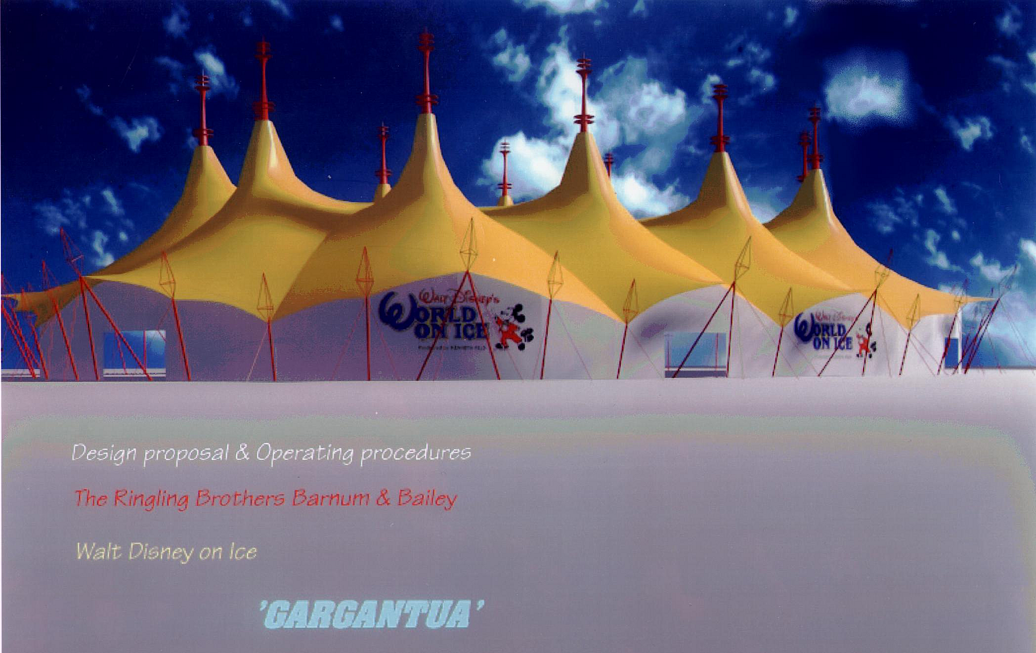
The exterior of Gargantua 1996
When Rudi designed the Kayam most tents looked like old-fashioned flower tents, made from canvas and in dirty white. Now 30 years later, there are few large-scale tents that don’t owe something to the Kayam’s design features. It is nessesary to explain why the design features work, and in some cases where they don’t. The Valhalla has very little that was arrived at by accident and the aerodynamics really work. It is probably the most technically advanced portable structure in the world, even after all these years.
With reference to using the structures with a reduced amount of side poles. Both structures were designed to allow the removal of most (Kayam – lacings and corners MUST remain) and all (Valhalla) of the side poles, provided there were no walls suspended from the structure. The result of this is to increase the side guy and anchor forces by roughly the amount of reduction of number of side masts. So, the worst case side pole load is 104.9 kN. See attached image. If there is a reduction of every 3rd sidepole the forces in the sidepole, side guy and anchors increases by 4, so roughly 40 tonnes. If you reduce the number of sidepoles but keep the side guys, the structure is at leas being restrained by the designed amount. Otherwise the forces in the roof and therefore the webbing sub system and the A frame all increase by the amount of side poles reduced. If you can show me a diagram of a typical corner and middle I can give you an indication of the increase in forces.
9.1 The side poles of Tensile 1 are not a safety critical item for the tent. Failure of the poles should not jeopardise the safety of the structure; providing it is being operated within the prescribed design limits and the tent has been properly maintained and erected.
9.2 The side poles have been designed on a modified basis to that which accords with the principles of BS5950. Traditionally the poles are interwoven with the sidewalls of the tent. Every second pole then acts in bending from the applied wind loads.
9.3 In the basic configuration Tensile 1 has side poles of between 6 to 8 metres in height, spaced at 2.25m centres. Wind acting on the membrane off-loads the sidepoles, and would put them into direct tension if they are anchored down sufficiently well.
9.4 Designing the poles for the wind induced bending moments would make the erection of the tent and poles beyond the capabilities of a single person, and would require the use of machinery. As the poles are only functioning when the tent is subjected to an applied down force; the design has been verified on that basis only.
9.5 When subjected to wind loads the poles are assumed to fail. By placing the poles outside of the sidewall on the windward side this failure mode would be averted. This would be an option for the tent-master under more extreme wind conditions.
9.6 For the axial loaded conditions the sidepoles comply with BS5950 in all regards with the exception of slenderness.
9.7 There are guys and storm guys on the line of the sidewalls at 1.125 metre centres. The number of potential side pole locations can be doubled if necessary. This facility will also enable the Tent-master to move internal side poles outside when required, or place additional external side poles on the windward side. By doubling the number of sidepoles the ability of the tent to resist vertical loads is enhanced.
Ideal conditions, i.e. Un-damaged fabric, properly erected, guyed to stiff foundations and anchors capable of taking the loads, and all of the structure in as new condition. A method of accurately forecasting and measuring site wind speed should be arranged.
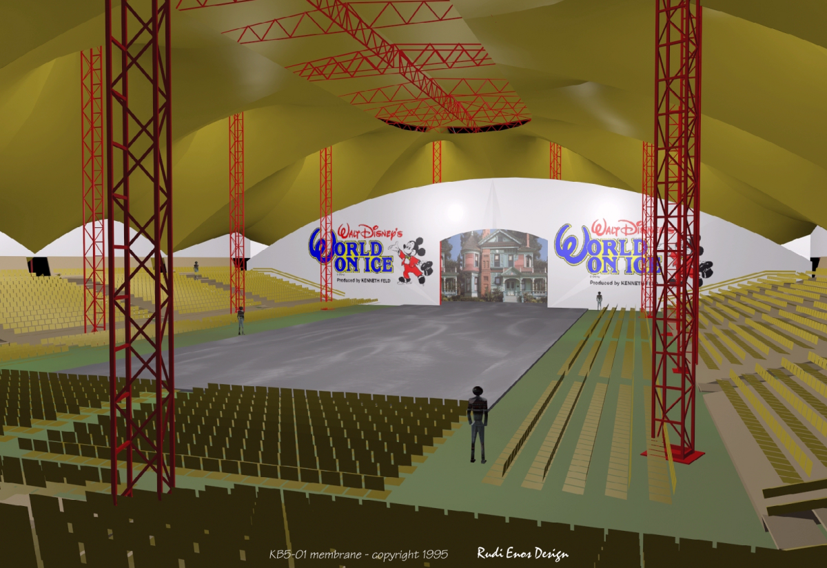
The interior of Gargantua 1996

One of the original renders of the concept 1997
The Development Of The Largest Portable Tensile Structures In The World
This proposal describes the 35 year development of the largest portable membrane supported structures ever built. Arena or football stadium roofs can be larger but are supported by steel or wire rope cables as in a suspension bridge. The long span structures designed by Rudi Enos are primarily supported by masts, but the remainder of these enormous structures use the tension membrane along with a hybrid fabric/webbing cablenet to accept the environmental forces. No steel wire rope cables are used in the membrane. It is probably the largest MEMBRANE supported roof in the world.
This document describes the original thinking, intense design required, the technical expertise and the use of advanced software to enable the manufacture of structural fabric portable roofs up to 12,000 square metres. It will also cover transport, deployment, rigging, lifting gear, safety issues and erection sequences of these special structures. Design process of portable tension structures compared to permanent versions. These structures use unique methods of achieving particular objectives. Traditionally, large permanent and mobile membrane structures rely on large diameter steel cables to provide control points. As the was to be a truly mobile membrane it was considered that extensive ground works (or large steel cables or reinforcement), other than staking would not be suitable. Certain methods of providing anchorage were used that had not been considered before.
Manufacturing engineering of the portable membrane structures. The making of parts and components (sometimes with the help of robots), is usually considered a subspecialty of mechanical engineering. The knowledge of 3D CAD-CAM, engineering design, fluid mechanics, structural computation, machine design, controls, robotics, operations, maintenance, and logistics are all involved in the portable project. All parts are designed with the aid of computer graphics. The computer carries out all the technical computations needed to make a part meet performance requirements. This aspect of computer-aided design (CAD) is frequently coupled with computer-aided manufacture (CAM) to produce parts automatically.
The scope of the works in the project comprised the design, supply, patterning, fabrication, delivery and erection of the fabric canopy together with the associated steelwork, cables and forks, anchors, and supporting steelwork.
The many different engineering functions to process the project included the following:
-
Research.
-
Development.
-
Design.
-
Manufacturing Specifications
-
Standards
-
Quality Control
-
Testing.
-
Materials Fabric assembly manufacture and testing.
-
Fabrication of Structural Fabric Sections
-
Drawings showing detailed arrangement of all joints and boundary Sewing and welding procedures and sequence.
-
Marking and numbering for the cloths. Full size drawings of corner details.
-
Field layout drawing showing cutting dimensions of fabric including stretch compensation and decompensation. Indications of places where smoothing curves will b required.
-
Positions of prepunched holes for all site fitted clamps. details.
-
A schedule of all shackles, ropes and fittings and a marking system for the same.
-
Steel fitting Details Testing of Fabric assemblies.
-
Steel assembly manufacture and testing.
-
Fabrication generally
-
Erection
Design and Specifications
Structure Type: It is a "tensile membrane structure," meaning the roof is made of a high-tech fabric (a PVC-coated polyester) pulled into shape by the tension from massive steel masts (poles) and cables.
Masts: The full version of the Valhalla can use up to 20 masts, each one standing 24 meters (80 feet) tall and weighing 3 tonnes. The 2004 EMA setup was a 10-pole version.
Dimensions: The complete Valhalla structure is enormous: 86 meters wide x 160 meters long x 25 meters high (282 ft x 600 ft x 82 ft). For the EMAs, it was configured to create over an acre (4,000+ square meters) of stage and floor space to accommodate the 6,000-person audience.
Self-Erecting: A key feature of its design is that it requires no external cranes for construction. It uses its own system of built-in power winches to raise the masts and pull the fabric membrane into place.
Fabric: The roof was made of a high-tenacity PVC-coated fabric (VALMEX 900), which is flame-retardant (meeting Italian Class 2 fire codes), waterproof, and resistant to cold.
Production and Load Capacity
This structure was famous in the event industry because it could handle the weight of a full-scale arena show.
Suspended Weight: The Valhalla can support up to 20,000 kg (20 tonnes) of equipment from each pair of masts.
2004 EMA Load: For the Rome show, the production crew suspended a staggering 88,000 kg (88 tonnes) of lighting rigs, video screens, speakers, and other staging elements directly from the structure's roof. This capability is what allowed MTV to build a high-tech television studio inside a temporary venue.
Technical Achievement Summary
The Tensile 1 structure represents the convergence of multiple engineering innovations creating the world's largest and most capable portable event venue:
Scale and Capacity:
- 12,600m² covered area (Guinness World Record)
- 240,000 kg suspended load capacity (arena-level performance)
- 16,600m² total structural surface including hybrid perimeter system
- 458-494 anchor foundation system with extensive distribution
Structural Innovation:
- Hybrid webbing/fabric membrane system optimizing materials by zone
- 350-360 radial webbing straps creating 4,000m² perimeter structure
- Complete replacement of steel cable with synthetic webbing
- 24 A-frame intermediate support system enabling controlled erection
- Purpose-built folding truss system (20,000 kg UDL capacity each)
Durability and Quality:
- Comprehensive hot-dipped galvanized protection (50+ year service life)
- Steel baseplate foundation system standardizing connections
- Professional engineering and computational design optimization
- Quality materials selected for long-term reusability
Functional Capability:
- Matches permanent arena performance in portable format
- Blackout membrane enabling controlled exhibition environment
- Accommodates diverse event types and requirements
- Professional standards throughout (lighting, HVAC, safety, accessibility)
Industry Impact
Tensile 1 transformed expectations for temporary event infrastructure by demonstrating:
Performance Parity: Portable structures can genuinely match permanent facilities in:
- Functional capacity (240-tonne rigging)
- Environmental control (blackout + comprehensive services)
- Safety and certification standards
- Professional presentation quality
- Operational sophistication
Design Innovation: Validated multiple innovative approaches now widely adopted:
- Hybrid material systems optimizing by structural zone
- Webbing replacing steel cable in large-span structures
- Extensive distributed anchor fields vs. concentrated loads
- Folding/portable systems achieving high capacity
- Purpose-designed erection support systems
Sustainability Thinking: Embodied principles now central to sustainable infrastructure:
- Design for disassembly and reuse
- Long service life through quality investment
- Adaptability serving diverse applications
- Resource efficiency through extended use
- Complete site restoration capability
- Multi-purpose vs. specialized single-use
Professional Standards: Influenced regulatory development and industry standards through:
- Designer participation in HSE/JACE working groups
- Successful high-profile deployments demonstrating capability
- Establishment of certification protocols
- Proof of concept for extreme temporary loading scenarios
- Validation of material and protection systems
Technical Significance
The engineering principles proven through Tensile 1 continue to influence temporary structure design:
Computational Design:
- Advanced nonlinear analysis for large membrane structures
- Integrated simulation of complex material interactions
- Form-finding and optimization methodologies
- Multi-load-case verification and safety factor confirmation
Material Science:
- High-strength synthetic webbing replacing traditional cable systems
- Hybrid material approaches optimizing performance and cost
- Long-term durability through systematic corrosion protection
- Quality investment justified by extended service life
Structural Systems:
- Distributed load strategies vs. concentrated force approaches
- Intermediate support systems controlling complex erection sequences
- Modular/portable designs achieving high absolute capacity
- Integration of building services in temporary structural frameworks
Foundation Technology:
- Screw anchor systems for extreme portable structure loads
- Steel baseplate standardization for rapid deployment
- Extensive anchor fields distributing vs. concentrating loads
- Immediate loading capability enabling compressed schedules
Continuing Relevance
More than two decades after its design, Tensile 1 remains:
Technically Relevant:
- Still among world's largest portable structures
- Capacity and capability competitive with modern designs
- Engineering principles and innovations still current
- Quality construction ensuring continued service life
Operationally Valuable:
- Continues to serve high-profile events worldwide
- Galvanized protection maintaining professional appearance
- Component durability enabling decades of continued use
- Adaptability to evolving event requirements and technologies
Professionally Significant:
- Benchmark for temporary structure capabilities
- Educational example of integrated engineering excellence
- Standard for comparison in portable venue specifications
- Proof of principle for ambitious temporary infrastructure
Final Assessment
Tensile 1 validates the principle that temporary infrastructure, when properly engineered with quality materials, sophisticated design, and long-term thinking, can deliver performance matching or exceeding permanent facilities while maintaining flexibility, reusability, and minimal environmental impact.
The structure demonstrates that "temporary" need not mean "compromise"—through innovative engineering, systematic optimization, and investment in quality, portable structures can achieve arena-level capacity, professional presentation standards, and decades of reliable service across diverse applications worldwide.
The technical innovations pioneered in Tensile 1—hybrid material systems, webbing-based tension structures, extensive distributed foundations, purpose-designed erection support, comprehensive durability protection, and massive portable suspended loads—established methodologies that continue to inform temporary structure engineering and advance the state of the art in portable event infrastructure.
Ref:
Technical Specifications and Engineering Analysis Compiled from: Special Structures Lab technical documentation, engineering specifications, material data sheets, structural analysis reports, installation procedures, and industry technical publications
next page - /book-page/before-this-the-kayam